-40%
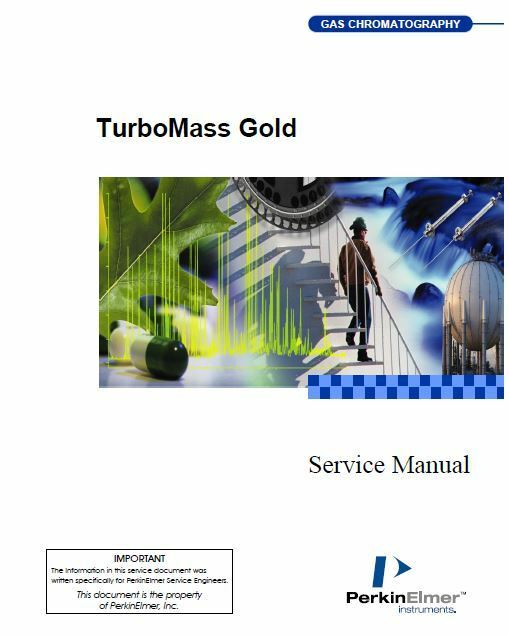
Perkin Elmer TurboMass Gold Service Manual
$ 66
- Description
- Size Guide
Description
Complete Service Manual for Perkin Elmer Turbomass GoldIncluded in the Service Manuals;
Table of Contents
- i -
Part I: Introduction
Chapter 1: Using this Manual
Using this Manual
Organization of this Manual
Overview of the TurboMass Gold Instrument
AutoSystem XL GC
TurboMass Gold Mass Spectrometer ................................................. 1-4
GC Interface (Transfer Line) .............................................................. 1-5
Reference Gas Inlet............................................................................. 1-5
Ion Optics Path ................................................................................... 1-7
Vacuum System................................................................................... 1-8
Minimum Computer Configuration.................................................... 1-9
System Requirements ......................................................................... 1-9
Specifications ........................................................................................... 1-11
Chapter 2: Safety and Regulatory Information
Safety and Regulatory Information ............................................................... 2-1
Safety and Regulatory Information ............................................................... 2-1
User Attentions.......................................................................................... 2-1
Customer Service ....................................................................................... 2-2
Electromagnetic Compatibility (EMC) ...................................................... 2-2
United States (FCC)............................................................................ 2-2
Symbols Used on TurboMass Gold............................................................ 2-3
Electrical ............................................................................................. 2-3
Label Location and Content................................................................ 2-4
TurboMass Gold Safety Practices.............................................................. 2-5
Generic Warnings ............................................................................... 2-5
Moving the TurboMass Gold............................................................... 2-5
Electrical High Voltage....................................................................... 2-5
Contamination..................................................................................... 2-6
Compressed Gases .............................................................................. 2-7
Ventilation........................................................................................... 2-7
Heated Zones....................................................................................... 2-8
Using Hydrogen, Methane or Isobutane ............................................ 2-8
Hazardous Chemicals ......................................................................... 2-9
Contents
- ii -
Definitions in Warning for Hazardous Chemicals ........................... 2-10
Temperature, Humidity, and Environment ............................................ 2-11
Operating Conditions........................................................................ 2-11
Storage Conditions............................................................................ 2-11
General Laboratory Safety ............................................................... 2-12
Part II: Installation
Chapter 3: Hardware Installation
Hardware Installation.................................................................................... 3-1
Hardware Installation.................................................................................... 3-1
Installation Summary................................................................................ 3-2
Pre-Installation Checklist.......................................................................... 3-2
TurboMass Gold Installation Checklist .................................................... 3-8
Unpack the TurboMass Gold Hardware ................................................. 3-12
Items in the TurboMass Gold Shipping Kit ..................................... 3-12
Items in the TurboMass Gold Spares............................................... 3-13
How to Unpack the Instrument........................................................ 3-14
Remove the Rotary Vane Pump from Its Shipping Carton ............. 3-15
Prepare the TurboMass Gold for Installation......................................... 3-17
Place the TurboMass Gold on your Lab Bench ................................ 3-17
Remove the TurboMass Gold Panels................................................ 3-18
Remove the EPCAS Module Assembly.................................................... 3-19
Remove the EPCAS Module Assembly............................................. 3-19
Check or Change the TurboMass Gold Voltage ...................................... 3-20
Install the Rotary Vane Pump................................................................. 3-21
Check or Change the Rotary Vane Pump Voltage ........................... 3-21
Add Oil to the Rotary Vane Pump.................................................... 3-23
Install the Penning Gauge....................................................................... 3-25
Install the Heated Transfer Line ............................................................ 3-26
Install the AutoSystem XL GC................................................................ 3-29
Install the Left-Side Panel................................................................ 3-29
Install the Computer and Monitor .......................................................... 3-30
Install the Start/Ready and GC Alarm Cable ......................................... 3-31
Connect the TurboMass Gold to the AutoSystem XL GC....................... 3-33
Connect the System Cables ..................................................................... 3-35
TurboMass Gold System with an Internal LINK ............................ 3-35
Connect the Gas Supplies........................................................................ 3-36
Cleaning the Gas Delivery Lines...................................................... 3-36
Pump-Down the System .......................................................................... 3-37
Contents
- iii -
How to Determine if a Vacuum Leak Exists.................................... 3-43
Configuring the GC for the First Time.................................................... 3-49
1. Select Configure on the top menu bar. ........................................ 3-49
2. Select Configure from the GC option that appears in the top menu
bar...................................................................................................... 3-50
3. Verify the Data Acquisition port. ................................................ 3-53
4. Set the LINK Configuration options. .......................................... 3-53
5. Set the GC Configuration options................................................ 3-54
Install the Column................................................................................... 3-59
Column Installation Summary......................................................... 3-59
1. Prepare the system to install the GC column. ............................ 3-60
2. Remove an installed column. ....................................................... 3-62
3. Connect one end of the new column to the GC injector. ............. 3-66
4. Condition the new column for use. .............................................. 3-70
5. Connect the other end of the new column to the TurboMass
Gold. ............................................................................................. 3-71
6. Equilibrate the system................................................................. 3-77
Check for Leaks........................................................................................ 3-78
Chapter 4: Software Installation
Software Installation...................................................................................... 4-1
Software Installation...................................................................................... 4-1
TurboMass Gold 4.3.0 Installation............................................................ 4-1
Equipment........................................................................................... 4-1
Reinstalling MS Windows NT 4.0 on the Dell Optiplex Computer.......... 4-2
Operating System Re-Installation...................................................... 4-2
System Configuration Prior to Installing TurboMass Gold Software4-4
Configure the Service Settings ........................................................... 4-4
Specify the Protocol............................................................................. 4-5
Specify the IP Address ........................................................................ 4-7
Configure the Microsoft Peer Web Server Settings ........................... 4-8
Set FTP Properties............................................................................ 4-10
Install NT 4.0 Service Pack 6a ......................................................... 4-14
Installing TurboMass Gold Software on the Dell Optiplex Computer... 4-15
Installing TurboMass NIST/EPA/NIH Library Dell Optiplex Computer4-18
Installing the Wiley and Pfleger/Maurer/Weber Libraries.............. 4-26
Chapter 5: Changing to the CI Mode
Changing to the CI Mode ............................................................................... 5-1
Changing to the CI Mode ............................................................................... 5-1
Overview..................................................................................................... 5-1
Hazardous Gas Warnings ................................................................... 5-1
Differences between Chemical and Electron Ionization .................... 5-2
About the EI and CI Inner Ion Sources.............................................. 5-2
Typical EI Parameters ........................................................................ 5-4
Setting Up to Run CI ................................................................................. 5-5
Connect the CI reagent gas................................................................. 5-5
Leak Check the System ...................................................................... 5-6
Tune for Electron Ionization (EI) ....................................................... 5-6
Set the CI parameters......................................................................... 5-8
Adjust the Reagent Gas for CI.......................................................... 5-11
Part III: Electronics
Chapter 6: Circuit Operation
Circuit Operation............................................................................................ 6-1
Circuit Operation............................................................................................ 6-1
Introduction to Circuit Operation ............................................................. 6-1
Abbreviations ............................................................................................. 6-2
Instrument Functions and Sections .......................................................... 6-3
Block Diagram of the TurboMass Gold Electronics ........................... 6-4
Functional Descriptions of Printed Circuit Boards ........................... 6-6
Printed Circuit Board Details.................................................................... 6-9
Scan Control Section........................................................................... 6-9
Analog Section.......................................................................................... 6-13
Heater Circuits.................................................................................. 6-13
Filament and Emission Control........................................................ 6-15
Lenses................................................................................................ 6-16
Analog DACs ..................................................................................... 6-17
Analog Readbacks ............................................................................. 6-17
RF and DC Generator .............................................................................. 6-17
RF Oscillator ..................................................................................... 6-19
DC Voltage Control ........................................................................... 6-20
DC Switching .................................................................................... 6-20
Contents
- v -
RF Power.................................................................................................. 6-21
Power Amplifier ................................................................................ 6-21
RF Rectifier and Thermal Trip......................................................... 6-21
Vacuum Pump Logic ................................................................................ 6-22
Pump Selected in TurboMass Gold .................................................. 6-22
Turbo speed > 80%............................................................................ 6-22
Vent selected in TurboMass Gold..................................................... 6-22
Digital I/O Software Specification........................................................... 6-22
Acquisition Interface................................................................................ 6-23
Chapter 7: Electronic Setup
Electronic Setup.............................................................................................. 7-1
Electronic Setup.............................................................................................. 7-1
Test Equipment Required.......................................................................... 7-1
Power Supplies........................................................................................... 7-1
High Voltage Supplies ........................................................................ 7-2
Photomultiplier Voltage...................................................................... 7-2
Voltage Interlocks ...................................................................................... 7-2
GC Interface Interlock ........................................................................ 7-3
Rotary / Turbo Pump Interlocks ......................................................... 7-3
Valves and Pumping .................................................................................. 7-4
Rotary Vane Pump.............................................................................. 7-6
Remove the EPCAS Module Assembly............................................... 7-7
Low Voltage Supplies.......................................................................... 7-9
Embedded PC Power Supply (Switching) .......................................... 7-9
Vacuum Measurement............................................................................. 7-11
Penning Gauge .................................................................................. 7-12
Source Parameters................................................................................... 7-14
Definitions ......................................................................................... 7-14
Preparing for Electronic Setup................................................................ 7-15
TurboMass Gold PCB Set-up................................................................... 7-15
Coutant 7.5 Volt Power Supply Adjustment .................................... 7-15
RF Bias Adjustment.......................................................................... 7-16
Filament Emission Regulation Setup............................................... 7-17
RF Tuning ......................................................................................... 7-19
RF Resolution Adjustment................................................................ 7-20
Instrument Resolution at High Mass............................................... 7-24
Readback Adjustment.............................................................................. 7-24
Dynode and Phosphor Supplies ............................................................... 7-25
Photomultiplier Supply............................................................................ 7-25
Head Amplifier Adjustment .................................................................... 7-26
Mass Scale Calibration ............................................................................ 7-27
Contents
- vi -
Hardware Coarse Calibration (Deglitch) ......................................... 7-27
Software Fine Calibration ................................................................ 7-31
Acquisition of FC-43 Reference Gas ................................................. 7-35
Backgrounds............................................................................................. 7-37
Vacuum Status.................................................................................. 7-37
Leak Checking................................................................................... 7-38
Background Scan .............................................................................. 7-38
CI Source and Valve Operation (Option) ................................................ 7-41
Chapter 8: Circuit Diagrams
TurboMass Gold Schematics…
…………………………………………………..8-3
TurboMass Gold Control PCB (14 Sheets)……………………………………..8-21
TurboMass Gold Cable Diagrams……………………………………………….8-49
Part IV: Troubleshooting and Maintenance
Chapter 9: Troubleshooting and Maintenance
Troubleshooting .............................................................................................. 9-1
Troubleshooting .............................................................................................. 9-1
Normal Operations .................................................................................... 9-1
TurboMass Gold Power on Sequence ................................................. 9-1
TurboMass Gold Power off Sequence ................................................. 9-2
TurboMass Gold GCMS PCB Notations.................................................... 9-4
Fault Finding Check Lists ......................................................................... 9-7
General Loss of Performance.............................................................. 9-7
Burst Cycle-noise that comes and goes looks like high frequency
oscillations........................................................................................... 9-9
Moderate Frequency-cycling of a regular duration from ½ second
to 2 seconds......................................................................................... 9-9
60 or 50 Cycle Frequency.................................................................... 9-9
Low frequency- Cycling every 12 to15 seconds ................................... 9-9
High Frequency Spikes....................................................................... 9-9
Transfer Line Heating Problem........................................................ 9-10
Problems Related to the Vacuum System ........................................ 9-10
TurboMass Leak Testing .................................................................. 9-12
Source Related Faults....................................................................... 9-13
Emission Regulation Problems......................................................... 9-15
Contents
- vii -
Ground and Chassis Checks.................................................................... 9-17
The Source................................................................................................ 9-18
Source ................................................................................................ 9-18
Transfer line J5................................................................................. 9-18
EPCAS / PC Communications ................................................................. 9-19
Hyperterminal Connection ............................................................... 9-20
Telnet Connection ............................................................................. 9-27
Key Source Voltage Monitoring points on the GCMS PCB ............. 9-30
Filament Voltage Set-up and Problems ........................................... 9-30
Additional Considerations ................................................................ 9-31
Chapter 10: Maintenance
Maintenance ................................................................................................. 10-1
Maintenance ................................................................................................. 10-1
Overview................................................................................................... 10-1
Electrostatic Discharge Information ................................................ 10-2
Maintenance Schedules ........................................................................... 10-2
Typical Maintenance......................................................................... 10-3
Routine Maintenance............................................................................... 10-3
TurboMass Gold Cleaning ................................................................ 10-3
About Gas Ballasting ........................................................................ 10-5
Active Inverted Magnetron (Penning) Gauges................................. 10-7
Miscellaneous Procedures................................................................. 10-7
Leak Checking.......................................................................................... 10-8
Tuning TurboMass Gold ........................................................................ 10-10
Preparing TurboMass Gold for Hardware Maintenance ...................... 10-13
Step 1. Turn off the Operate Mode................................................ 10-13
Step 2. Cool the Transfer Line, GC Column Oven, and Source.... 10-13
Step 3. Vent the System................................................................. 10-14
Step 4. Turn off the GC Carrier Gas ............................................. 10-14
Changing a Column ............................................................................... 10-15
Removing a Column........................................................................ 10-15
Connect the New Column to the Split/Splitless Injector ............... 10-16
Connecting a New Column to TurboMass Gold ............................. 10-20
Refilling the Reference Gas Vial............................................................ 10-26
Inner Source Maintenance..................................................................... 10-28
Removing the Inner Source ............................................................ 10-28
EI Inner Source Maintenance......................................................... 10-30
Reassembling .................................................................................. 10-33
CI Inner Source Maintenance......................................................... 10-35
Contents
- viii -
Reinstalling the Source................................................................... 10-39
Replacing a Filament ............................................................................. 10-40
Replacing the Head Amplifier ............................................................... 10-44
Mass Analyzer Maintenance ................................................................. 10-46
Removing the Ion Optics Assembly ................................................ 10-47
Replacing an Outer Source Thermocouple ..................................... 10-55
Removing the Outer Source from the Ion Optics ........................... 10-57
Replacing Outer Source Heaters .................................................... 10-58
Replacing the Quadrupole Heater.................................................. 10-59
Cleaning the Outer Source Lens .................................................... 10-61
Reassembling the Ion Optics Assembly ......................................... 10-63
Reassembling TurboMass Gold ............................................................. 10-66
Vacuum System Maintenance ............................................................... 10-67
Checking the Rotary Vane Pump Oil Level ................................... 10-68
Adding Oil to the Rotary Vane Pump Reservoir ............................ 10-69
Decontaminating the Oil................................................................. 10-69
Replacing the Pump Oil.................................................................. 10-70
Replacing Fuses ..................................................................................... 10-72
Replacing the Turbopump Controller.................................................... 10-73
Replacing the Turbopump ..................................................................... 10-77
Penning Gauge Maintenance................................................................. 10-79
Replace the Body Tube.................................................................... 10-79
Replace the Electrode Assembly..................................................... 10-81
Replace the Electronics and Magnet Housing ............................... 10-82
Clean the Internal Components ..................................................... 10-82
Pirani Gauge Maintenance.................................................................... 10-83
Clean the Filter ............................................................................... 10-84
Attached photos show the TOC, and some of the diagrams and illustrations to show the quality of this manual
Once purchased the link to the Compressed files (English) may be sent via Googledrive share for download, or emailed (size dependent)
Note: Other service, operator, manuals are available as well as training materials (powerpoint, video, full training course material) - please contact about availability.
Please feel free to contact us with any questions.


